
- All
- Product Name
- Product Keyword
- Product Model
- Product Summary
- Product Description
- Multi Field Search
 |


| Quantity: | |
|---|---|
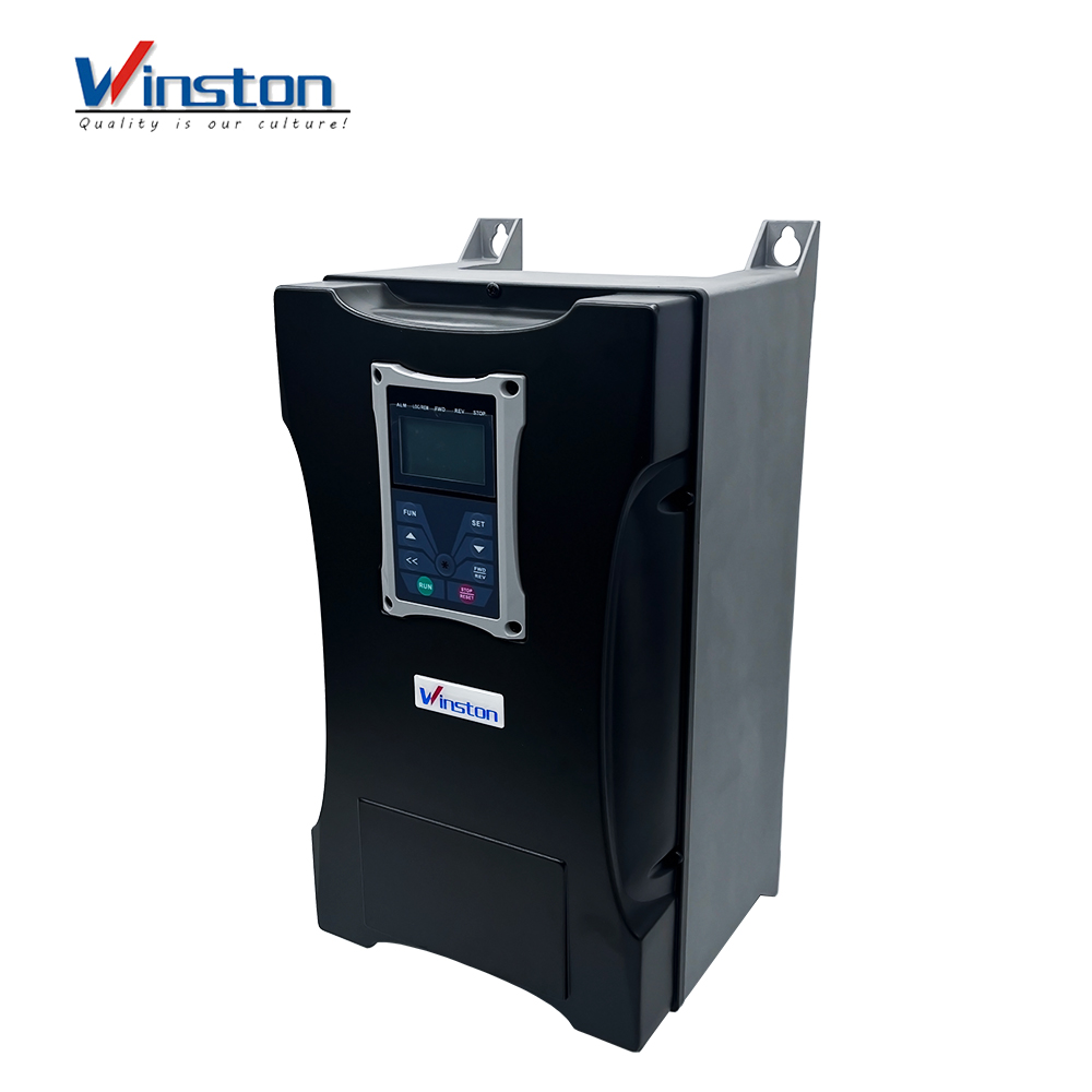
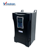
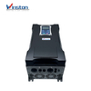
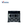
WP66
Winston
● DSP based high-tech motor control concept, suitable for V/Hz, SENSORLESS VECTOR, PMM synchronous motor control,SPEED/TORQUE control mode
● Intelligent AUTOTUNING functions for quick and easy set-up
● Rugged construction, IP66/NEMA 4
● Flexible configurable 4 line character display - ready for any common field bus
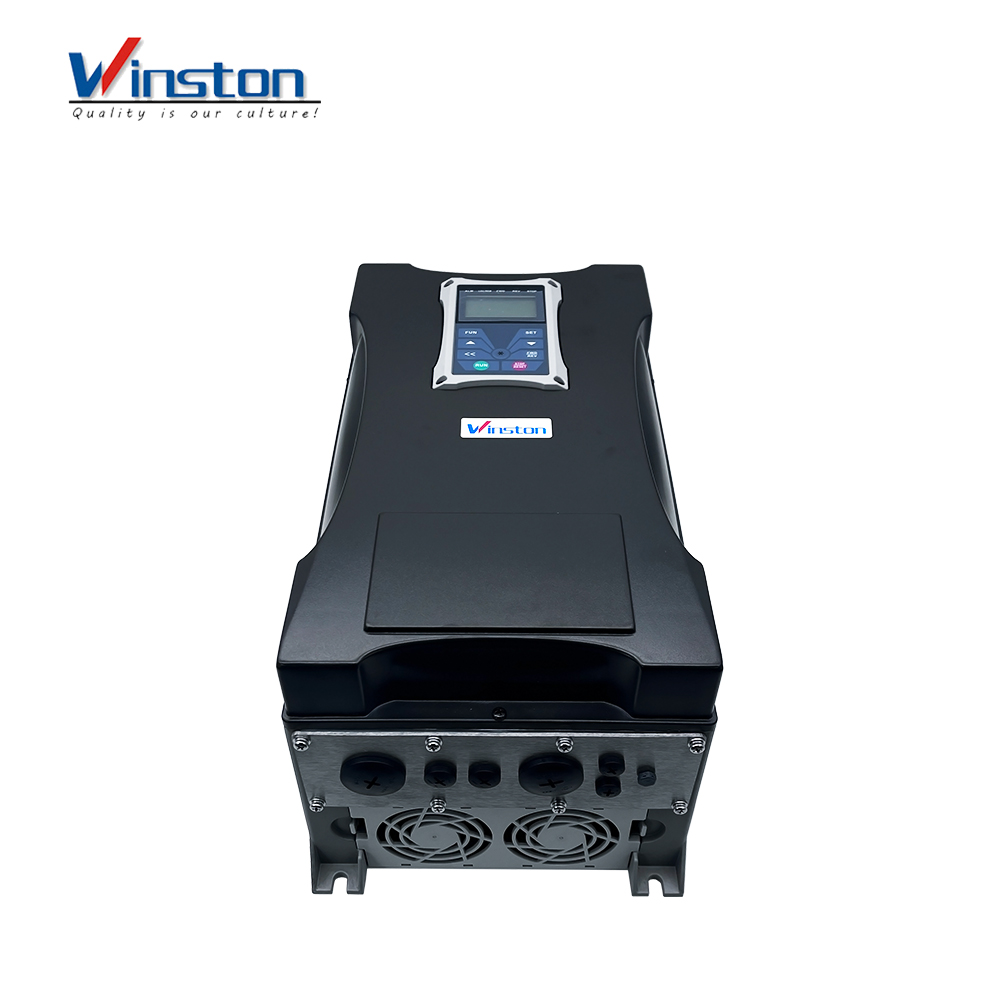
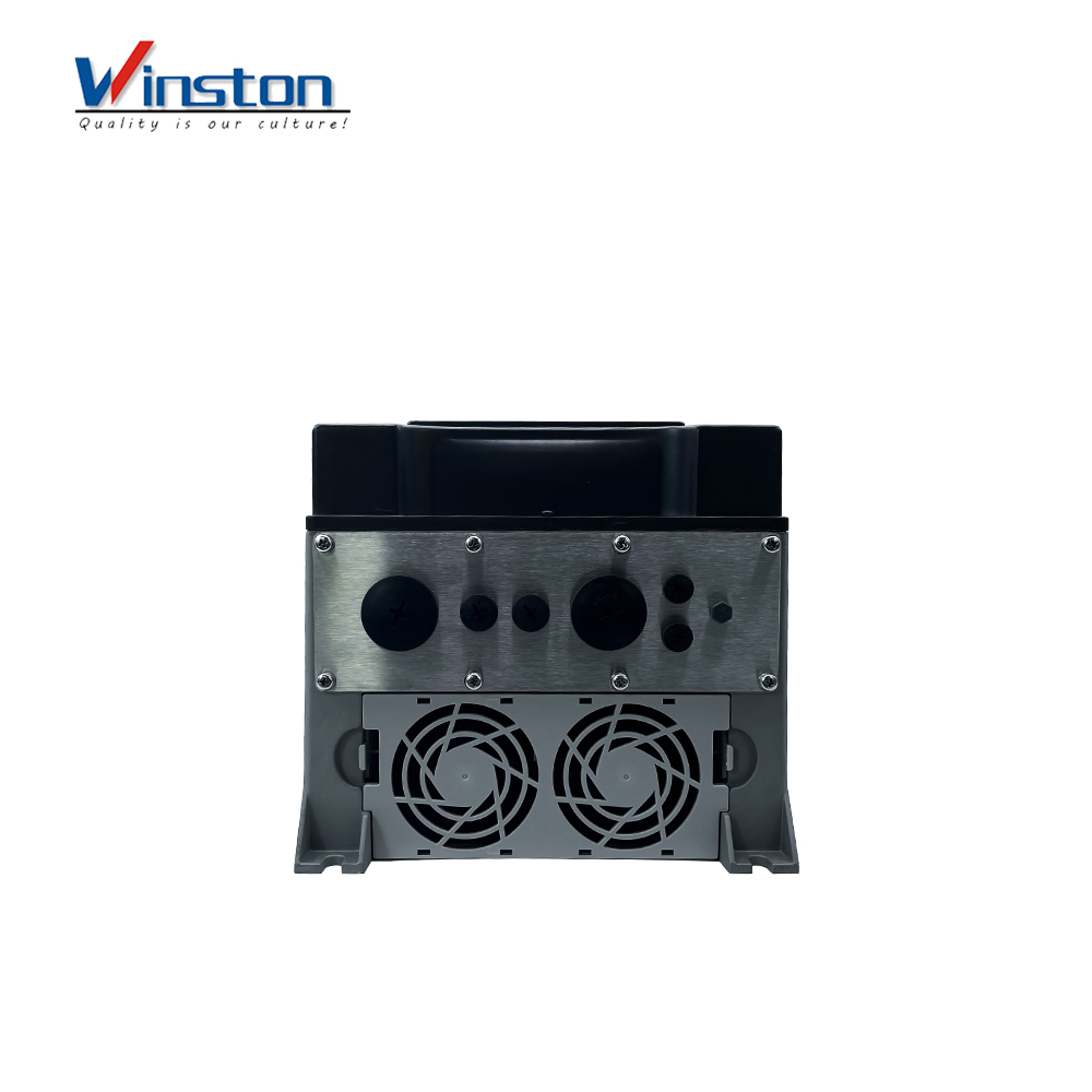
● Removable cable conduit plate, including vent with humidity barrier
● Space inside the drive for customer options like, main/emergency switch, start/stop selectors, potentiometer and brake resistor
● Optional BYPASS switch built in
● C3 class filter standard — optional C1 EMC filter build in for 1. Environment (residential area)
● All standard inverter functions built in, to make it suitable for various industrial,civil,and retrofit applications
● Smart PC-tools, for inverter control, parametrization and troubles hooting. parameter-duplication stick
● Ready for the worldwide market, due to approved international standards
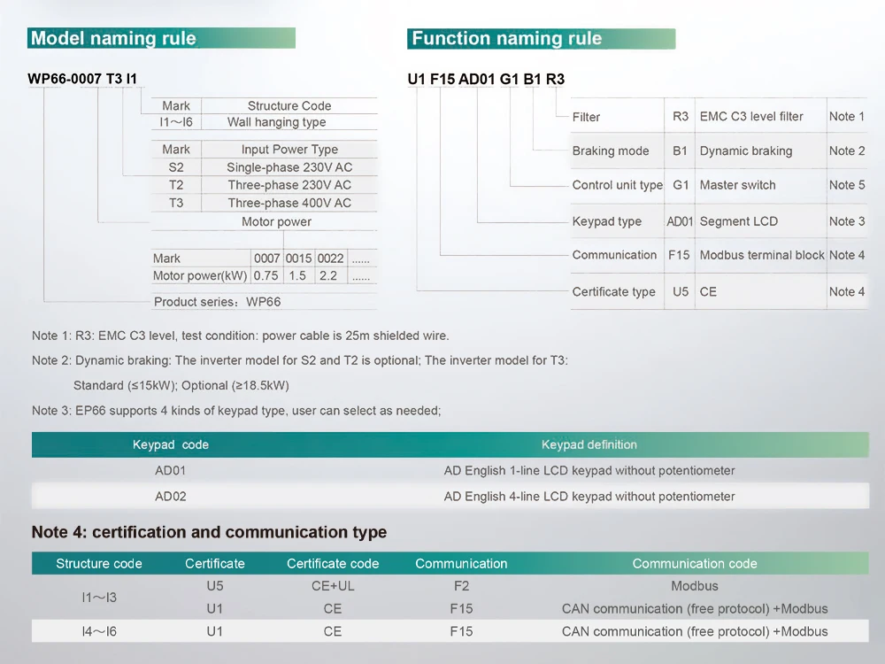
Model Explanation
Technical parameter
| Items | Contents | |
| Input | Rated Voltage Range | T3 380V-480V +10%/-15%; S2/T2 220V-240V±15% |
| Rated Frequency | 50/60Hz | |
| Output | Rated Voltage Range | 3-phase 0-Input |
| Frequency Range | 0.50~650.0Hz | |
| Control Mode | Carrier Frequency | 800-16000Hz; Fixed carrier-wave and random carrier-wave can be selected by F159. |
| Input Frequency Resolution | Digital setting: 0.01Hz; Analog setting: Max frequency 0.1% | |
| Control Mode | Sensorless Vector Control (open-loop vector control)V/F control, PMSM sensorless vector control | |
| Start Torque | 0.5 Hz/ 150% (SVC), 5% of rated speed / 100% of rated torque (PMSM) | |
| Speed-control Scope | 1:100 (SVC), 1:20 (PMSM) | |
| Steady Speed Precision | ±0.5% (SVC) | |
| Torque Control Precision | ±5% (SVC) | |
| Overload Capacity | 150% rated current, 60 seconds. | |
| Torque Elevating | Auto torque promotion, manual torque promotion includes 1-20 curves. | |
| V/F Curve | 3 kinds of modes: beeline type, square type and under-defined V/F curve. | |
| Startup mode | Direct startup, speed track startup (V/F control) | |
| DC Braking | DC braking frequency: 0.2-50.00 Hz, braking time: 0.00-30.00s | |
| Jogging Control | Jogging frequency range: Min frequency~ Max frequency, Jogging acceleration/ deceleration time: 0.1-30.00s | |
| Auto Circulating Running and multi-stage speed running | Auto circulating running or terminals control can realize 15-stage speed running. | |
| Built-in PID adjusting | Easy to realize a system for process closed-loop control | |
| Auto voltage regulation (AVR) | When the source voltage changes, the modulation rate will be adjusted automatically, resulting in an unchanged output voltage | |
| Operation Function | Frequency Setting | Potentiometer or external analog signal (0-5V, 0-10V, 0-20mA); keypad (terminal).▲/▼keys, external control logic and automatic circulation setting. |
| Start/Stop Control | Terminal control, keypad control or communication control. | |
| Running Command Channels | 3 kinds of channels from keypad panel, control terminal and MODBus. | |
| Frequency Source | Frequency sources: given digit, given analog voltage, given analog current and given MODBUS | |
| Accessorial frequency Source | 6 kinds of accessorial frequency | |
| Optional | Built-in EMI filter, built-in braking unit, Modbus, tele-control panel | |
| Protection Function | Input phase loss, Output phase loss, input under-voltage, DC over-voltage, over-current, inverter over-load, motor overload, current stall, over-heat, external disturbance, under-load, pressure control, analog line disconnected, oPEn fault,STO function. | |
| Display | Output frequency, rotate-speed (rpm/min), output current, output voltage, DC bus voltage, PID feedback value, PID setting value, linear-velocity, types of faults, and parameters for the system and operation; LED indicators showing the current working status of inverter. | |
| Environment Conditions | Equipment Location | In harsh conditions, prevent dust of other thing from entering inverter totally. Completelyprotected against jets of water and heavy waves. Meeting EN 60529 standard. |
| Enuironmont Tomperatura | -10℃~+40℃ | |
| Vibration Strength | Below 0.5g (acceleration) | |
| Height above sea level | 1000m or below (derating use if higher than 1000m) | |
| Protection level | IP66 | |
| Class of pollution | PD2 | |
| Applicable Motor | 0.4~90kW | |
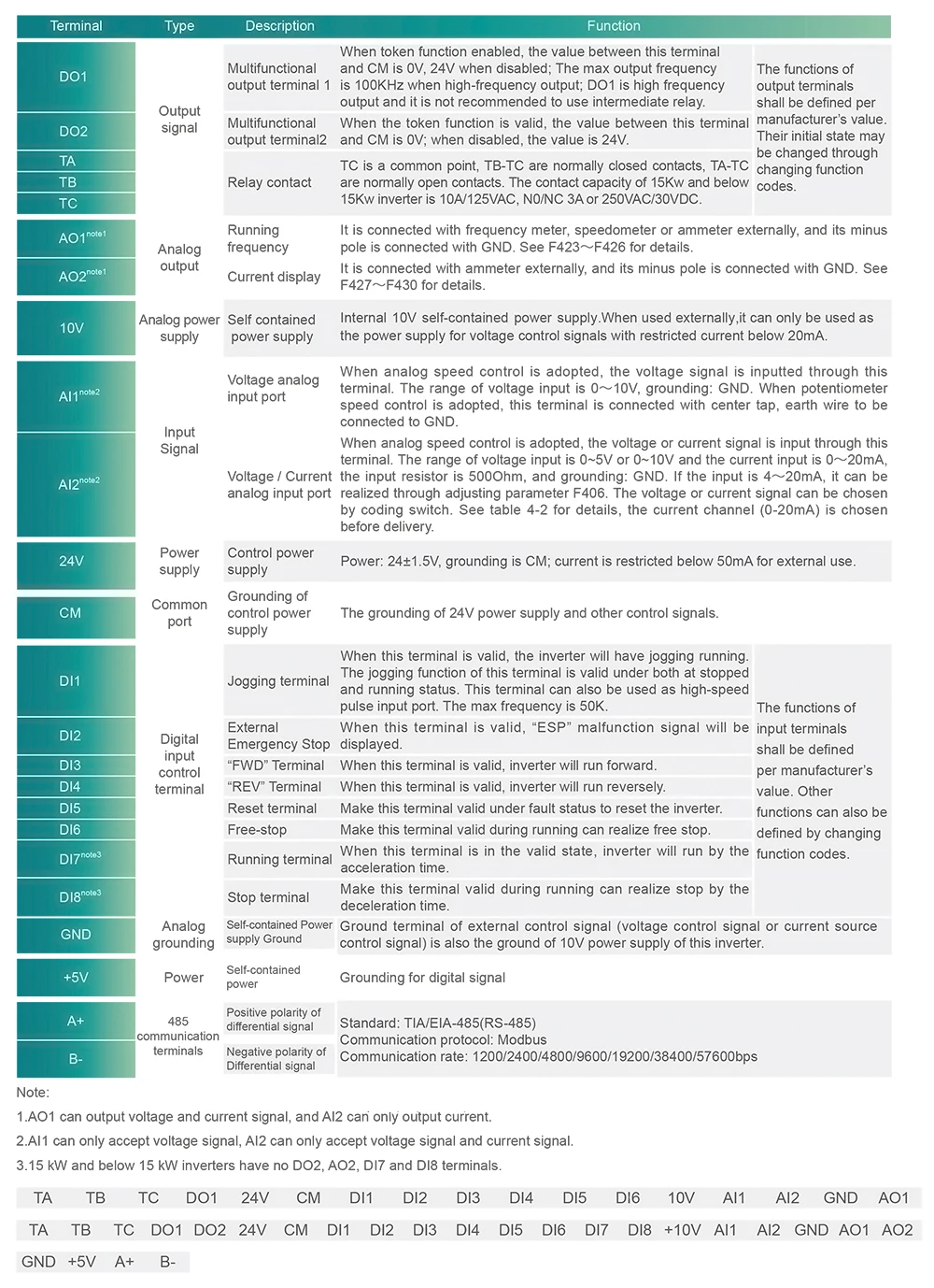
Functioning
| Model | Rated current | Remote Keypad | Structure code | Wright(kg) | Dimension (WxHxD-mm) | Cooling mode | Remarks |
| WP66-0004S2 | 0.4kW-2.5A | AD-A-1 Or AD-A-2 | I1 | 6.2 | 200×412×198 | Self cooling | Single-phaseplastic hanging |
| WP66-0007S2 | 0.75kW-4.5A | I1 | 6.2 | 200×412×198 | Self cooling | ||
| WP66-0015S2 | 1.5kW-7A | I1 | 6.2 | 200×412×198 | Self cooling | ||
| WP66-0022S2 | 2.2kW-10A | I1 | 6.2 | 200×412×198 | Air cooling | ||
| WP66-0004T2 | 0.4kW-2.5A | I1 | 6.2 | 200×412×198 | Self cooling | Three-phase plastic hanging | |
| WP66-0007T2 | 0.75kW-4.5A | I1 | 6.2 | 200×412×198 | Self cooling | ||
| WP66-0015T2 | 1.5kW-7A | I1 | 6.2 | 200×412×198 | Self cooling | ||
| WP66-0022T2 | 2.2kW-10A | I1 | 6.2 | 200×412×198 | Air cooling | ||
| WP66-0004T3 | 0.4kW-1.2A | I1 | 6.2 | 200×412×198 | Self cooling | ||
| WP66-0007T3 | 0.75kW-2A | I1 | 6.2 | 200×412×198 | Self cooling | ||
| WP66-0015T3 | 1.5kW-4A | I1 | 6.2 | 200×412×198 | Self cooling | ||
| WP66-0022T3 | 2.2kW-6.5A | I1 | 6.2 | 200×412×198 | Air cooling | ||
| WP66-0030T3 | 3.0kW-7A | I1 | 6.2 | 200×412×198 | Air cooling | ||
| WP66-0040T3 | 4.0kW-9A | I1 | 6.2 | 200×412×198 | Air cooling | ||
| WP66-0055T3 | 5.5kW-12A | I2 | 8.2 | 242×418×198 | Air cooling | ||
| WP66-0075T3 | 7.5kW-17A | I2 | 8.2 | 242×418×198 | Air cooling | ||
| WP66-0110T3 | 11kW-23A | I3 | 11.3 | 242×471×228 | Air cooling | ||
| WP66-0150T3 | 15kW-32A | I3 | 11.3 | 242×471×228 | Air cooling | ||
| WP66-0185T3 | 18.5kW-38A | I4 | 25 | 242×650×325 | Air cooling | Three-phase metal hanging | |
| WP66-0220T3 | 22kW-44A | I4 | 25 | 242×650×325 | Air cooling | ||
| WP66-0300T3 | 30kW-60A | I4 | 25 | 242×650×325 | Air cooling | ||
| WP66-0037T3 | 37kW-75A | I5 | 40 | 308×680×379 | Air cooling | ||
| WP66-0450T3 | 45kW-90A | I5 | 40 | 308×680×379 | Air cooling | ||
| WP66-0550T3 | 55kW-110A | I5 | 40 | 308×680×379 | Air cooling | ||
| WP66-0750T3 | 75kW-150A | I6 | 57 | 370×770×404 | Air cooling | ||
| WP66-0900T3 | 90kW-180A | I6 | 57 | 370×770×404 | Air cooling |
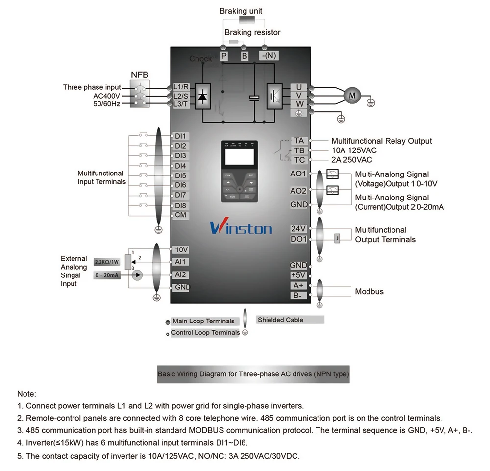
Wiring diagram

● DSP based high-tech motor control concept, suitable for V/Hz, SENSORLESS VECTOR, PMM synchronous motor control,SPEED/TORQUE control mode
● Intelligent AUTOTUNING functions for quick and easy set-up
● Rugged construction, IP66/NEMA 4
● Flexible configurable 4 line character display - ready for any common field bus
● Removable cable conduit plate, including vent with humidity barrier
● Space inside the drive for customer options like, main/emergency switch, start/stop selectors, potentiometer and brake resistor
● Optional BYPASS switch built in
● C3 class filter standard — optional C1 EMC filter build in for 1. Environment (residential area)
● All standard inverter functions built in, to make it suitable for various industrial,civil,and retrofit applications
● Smart PC-tools, for inverter control, parametrization and troubles hooting. parameter-duplication stick
● Ready for the worldwide market, due to approved international standards
Model Explanation
Technical parameter
| Items | Contents | |
| Input | Rated Voltage Range | T3 380V-480V +10%/-15%; S2/T2 220V-240V±15% |
| Rated Frequency | 50/60Hz | |
| Output | Rated Voltage Range | 3-phase 0-Input |
| Frequency Range | 0.50~650.0Hz | |
| Control Mode | Carrier Frequency | 800-16000Hz; Fixed carrier-wave and random carrier-wave can be selected by F159. |
| Input Frequency Resolution | Digital setting: 0.01Hz; Analog setting: Max frequency 0.1% | |
| Control Mode | Sensorless Vector Control (open-loop vector control)V/F control, PMSM sensorless vector control | |
| Start Torque | 0.5 Hz/ 150% (SVC), 5% of rated speed / 100% of rated torque (PMSM) | |
| Speed-control Scope | 1:100 (SVC), 1:20 (PMSM) | |
| Steady Speed Precision | ±0.5% (SVC) | |
| Torque Control Precision | ±5% (SVC) | |
| Overload Capacity | 150% rated current, 60 seconds. | |
| Torque Elevating | Auto torque promotion, manual torque promotion includes 1-20 curves. | |
| V/F Curve | 3 kinds of modes: beeline type, square type and under-defined V/F curve. | |
| Startup mode | Direct startup, speed track startup (V/F control) | |
| DC Braking | DC braking frequency: 0.2-50.00 Hz, braking time: 0.00-30.00s | |
| Jogging Control | Jogging frequency range: Min frequency~ Max frequency, Jogging acceleration/ deceleration time: 0.1-30.00s | |
| Auto Circulating Running and multi-stage speed running | Auto circulating running or terminals control can realize 15-stage speed running. | |
| Built-in PID adjusting | Easy to realize a system for process closed-loop control | |
| Auto voltage regulation (AVR) | When the source voltage changes, the modulation rate will be adjusted automatically, resulting in an unchanged output voltage | |
| Operation Function | Frequency Setting | Potentiometer or external analog signal (0-5V, 0-10V, 0-20mA); keypad (terminal).▲/▼keys, external control logic and automatic circulation setting. |
| Start/Stop Control | Terminal control, keypad control or communication control. | |
| Running Command Channels | 3 kinds of channels from keypad panel, control terminal and MODBus. | |
| Frequency Source | Frequency sources: given digit, given analog voltage, given analog current and given MODBUS | |
| Accessorial frequency Source | 6 kinds of accessorial frequency | |
| Optional | Built-in EMI filter, built-in braking unit, Modbus, tele-control panel | |
| Protection Function | Input phase loss, Output phase loss, input under-voltage, DC over-voltage, over-current, inverter over-load, motor overload, current stall, over-heat, external disturbance, under-load, pressure control, analog line disconnected, oPEn fault,STO function. | |
| Display | Output frequency, rotate-speed (rpm/min), output current, output voltage, DC bus voltage, PID feedback value, PID setting value, linear-velocity, types of faults, and parameters for the system and operation; LED indicators showing the current working status of inverter. | |
| Environment Conditions | Equipment Location | In harsh conditions, prevent dust of other thing from entering inverter totally. Completelyprotected against jets of water and heavy waves. Meeting EN 60529 standard. |
| Enuironmont Tomperatura | -10℃~+40℃ | |
| Vibration Strength | Below 0.5g (acceleration) | |
| Height above sea level | 1000m or below (derating use if higher than 1000m) | |
| Protection level | IP66 | |
| Class of pollution | PD2 | |
| Applicable Motor | 0.4~90kW | |
Functioning
| Model | Rated current | Remote Keypad | Structure code | Wright(kg) | Dimension (WxHxD-mm) | Cooling mode | Remarks |
| WP66-0004S2 | 0.4kW-2.5A | AD-A-1 Or AD-A-2 | I1 | 6.2 | 200×412×198 | Self cooling | Single-phaseplastic hanging |
| WP66-0007S2 | 0.75kW-4.5A | I1 | 6.2 | 200×412×198 | Self cooling | ||
| WP66-0015S2 | 1.5kW-7A | I1 | 6.2 | 200×412×198 | Self cooling | ||
| WP66-0022S2 | 2.2kW-10A | I1 | 6.2 | 200×412×198 | Air cooling | ||
| WP66-0004T2 | 0.4kW-2.5A | I1 | 6.2 | 200×412×198 | Self cooling | Three-phase plastic hanging | |
| WP66-0007T2 | 0.75kW-4.5A | I1 | 6.2 | 200×412×198 | Self cooling | ||
| WP66-0015T2 | 1.5kW-7A | I1 | 6.2 | 200×412×198 | Self cooling | ||
| WP66-0022T2 | 2.2kW-10A | I1 | 6.2 | 200×412×198 | Air cooling | ||
| WP66-0004T3 | 0.4kW-1.2A | I1 | 6.2 | 200×412×198 | Self cooling | ||
| WP66-0007T3 | 0.75kW-2A | I1 | 6.2 | 200×412×198 | Self cooling | ||
| WP66-0015T3 | 1.5kW-4A | I1 | 6.2 | 200×412×198 | Self cooling | ||
| WP66-0022T3 | 2.2kW-6.5A | I1 | 6.2 | 200×412×198 | Air cooling | ||
| WP66-0030T3 | 3.0kW-7A | I1 | 6.2 | 200×412×198 | Air cooling | ||
| WP66-0040T3 | 4.0kW-9A | I1 | 6.2 | 200×412×198 | Air cooling | ||
| WP66-0055T3 | 5.5kW-12A | I2 | 8.2 | 242×418×198 | Air cooling | ||
| WP66-0075T3 | 7.5kW-17A | I2 | 8.2 | 242×418×198 | Air cooling | ||
| WP66-0110T3 | 11kW-23A | I3 | 11.3 | 242×471×228 | Air cooling | ||
| WP66-0150T3 | 15kW-32A | I3 | 11.3 | 242×471×228 | Air cooling | ||
| WP66-0185T3 | 18.5kW-38A | I4 | 25 | 242×650×325 | Air cooling | Three-phase metal hanging | |
| WP66-0220T3 | 22kW-44A | I4 | 25 | 242×650×325 | Air cooling | ||
| WP66-0300T3 | 30kW-60A | I4 | 25 | 242×650×325 | Air cooling | ||
| WP66-0037T3 | 37kW-75A | I5 | 40 | 308×680×379 | Air cooling | ||
| WP66-0450T3 | 45kW-90A | I5 | 40 | 308×680×379 | Air cooling | ||
| WP66-0550T3 | 55kW-110A | I5 | 40 | 308×680×379 | Air cooling | ||
| WP66-0750T3 | 75kW-150A | I6 | 57 | 370×770×404 | Air cooling | ||
| WP66-0900T3 | 90kW-180A | I6 | 57 | 370×770×404 | Air cooling |
Wiring diagram